

INTRODUCTION
During the last few decades, the sedimentary record of palaeoearthquakes has been intensively studied by geologists (e.g., McCalpin, 1996, Levi at al., 2006; Li et al., 2008; Shamunghan, 2016, 2017). Sedimentologists have discovered the widespread occurrences of syndepositional sediment deformations attributable to earthquakes commonly termed as “seismites’’ in marine sedimentary strata (e.g., Seilacher, 1969; Van Loon et al., 2016; Shamunghan, 2016, 2017 and references herein). The term seismite is often used for the deformation structures of soft or wet sediments associated with earthquake-induced liquefaction or fluidisation (Moretti et al., 2001; Moretti & Sabato, 2007; Van Loon, 2009; Mugnier et al., 2013). However, Shanmugam (2016) and Van Loon et al. (2016) concluded that the term “seismite” is obsolete. Nevertheless, the term “seismite” should be strictly used for the beds with SSDS which are caused by the earthquakes (Feng, 1917; Shanmugam, 2016, 2017; Santos & Henrique-Pinto, 2022; Pati & Singh, 2023). Seilacher (1969, 1984) used the term seismite to describe the genetic category of faults created by biperiodic events such as earthquakes. Recently, most authors used term soft-sediment deformation structures (SSDS) to refer to liquefaction. They are the result of different processes such as liquefaction or fluidisation of water-saturated sediments (Sims, 1973; Lowe, 1975; Allen, 1982, 1984; Moretti, 2000; Van Loon, 2009; Owen & Moretti, 2011; Owen et al., 2011a; Shanmugam, 2016; Van Loon et al., 2016a; Feng et al., 2016; Feng, 2017a-b; Guo et al., 2023). Soft sediment deformation involves the plastic deformation that occurs when pore fluid pressure is rapidly exceeded in the sediment. This process is due to liquefaction or fluidisation of the sediment shortly after deposition. The genetic processes of liquefaction and fluidisation are slightly different and can lead to different types and forms of deformation structures (Tab. 2) (Owen, 1996; Alfaro et al., 1997; Moretti, 2000; Davies et al., 2004; Singh & Jain, 2007; van Loon, 2009; Owen et al., 2011a-b; Rossetti et al., 2017).
Several factors can trigger formation of SSDS such as earthquakes, tsunamis, floods, storm waves, shallow gravity landslides, groundwater movement, steep sedimentary slopes as well as increased sediment load (Allen, 1982; Mills, 1983; Owen, 1987; Moretti et al., 2001; Moretti & Sabato, 2007; Owen & Moretti, 2011; Moretti et al., 2016; Shanmugam, 2016, 2017; Feng, 2017a; Wang et al., 2020; Zhong, 2021).
The formation of SSDS could be the result of one of the aforementioned processes as well as the result of the interplay of more than one process. Sheared stress induced by earthquakes can trigger the fluidisation of water-saturated sediment (usually sand and silt), and lead to dynamic loading. This can later induce structural changes in the affected sediment and increased pore fluid pressure to a level equal to the overlying pressure. Seismic shocks can induce numerous effects in soft sediments; one of the most spectacular is liquefaction. Seismic liquefaction occurs when loose, saturated sandy soil loses its strength and stiffness due to strong ground shaking from an earthquake, causing it to behave like a liquid. This phenomenon is triggered by a rapid increase in pore-water pressure within the soil, which reduces the contact forces between soil particles, leading to a loss of shear strength. (e.g., Allen, 1982; Cavallaro et al., 2018).
Sand can be liquefied when it is water-saturated, but it occurs only in sands with a specific grain-size (Lowe, 1975; Obermeier, 1996). The soft-sediment deformation phenomena and seismic-related liquefaction are common worldwide (Shanmugam, 2016, 2017), especially in orogenic chains where earthquakes are common (Galli, 2000; Singh et al., 2020; Wozniak et al., 2021).
Liquefaction triggered by seismic shocks is common at the magnitude Ms ≥ 5.0, which is considered as the minimum magnitude capable of inducing the liquefaction; earthquakes with such magnitude can turn the sediments from grain supported to fluid supported state (e.g. Sim, 1975; Ambraseys, 1988; Leeder, 1987; Obemeir, 1996; Blanc et al., 1998; Qiao et al., 1998; Morner, 2005; Green & Bommer, 2019). However, Galli (2000) proposed a slightly lower limit Ms ≥ 4.2 for the onset of seismic-related liquefaction.
SSDS have a stratigraphic record from the Paleoproterozoic to the recent and they occur in different sedimentary settings (Sims, 1975; Owen, 1995; Moretti et al., 1999; Zhang et al., 2007; Shanmugam, 2016, 2017; Green & Bommer, 2019; Singh et al., 2020).
The main aims of this paper are: 1) to describe a complex of soft-sediment deformation structures; 2) to discuss the formation of sediment deformation structures and link them to the possible triggering agents; 3) to analyze formation of these SSDS in the framework of the local tectonic and volcanic activity.
GEOGRAPHIC AND GEOLOGIC SETTINGS
The study area part of the Tafna Basin, which is one of the Neogene Basins (Chlef and Metidja) oriented parallel to the Algerian coast. The study area is called Hadjret El Gat, and it is bordered by the Sabaa Chioukh Mountains to the NE, the Tessala Mountains to the E, the Tlemcen Mountain to the S and the Trara Mountains to the W (Fig. 1A and B).
- Location of the studied area. (A) Geographic map showing location of the studied section within the Tafna Basin (NW Algeria), (B) Location of the studied section within the Mediterranean Basin, (C) Geological map of the Tafna Basin, 1 - Paleozoic (Carboniferous), 2 - Triassic, 3 - Lower Jurassic, 4 - Middle Jurassic, 5 - Upper Jurassic, 6 - Lower Cretaceous, 7 - Upper Cretaceous, 8 - Oligocene, 9 - lower Eocene, 10 - upper Eocene, 11 - Lower Miocene, 12 - Middle Miocene, 13 - Upper Miocene, 14 - Pliocene, 15 - Old Quaternary, 16 - Recent Quaternary, 17 - Igneous Rocks (basalt and tufa), 18 - Dolerite and tufa.
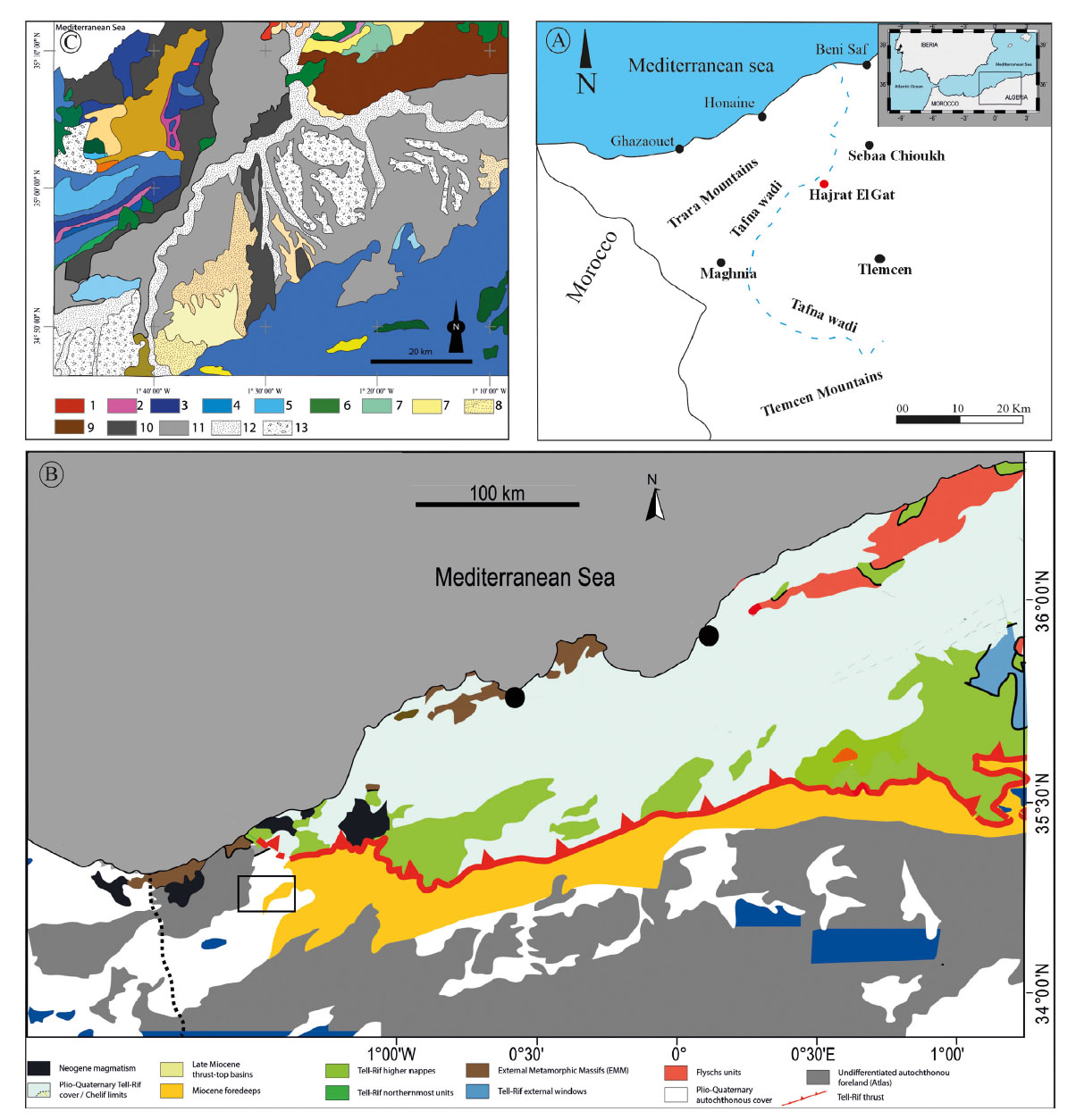
The Tafna Basin is mostly filled by Miocene-age deposits, overlying a Cretaceous substratum, consisting of yellowish shale (Guardia, 1975) (Fig. 1C). The Lower Miocene unit comprises conglomerates composed of rounded to sub-rounded clasts of limestone and dolostone. The conglomerate unit is up to 20m thick. Greenish marly clay overlies the conglomerates, and comprise thick to very thick sandstone beds. The studied Serravallian interval contains thick intercalations of sandstone and marl (Perrodon, 1957; Guardia, 1975). Volcanic rocks (basalt) partially overlie the Serravallian-age deposits.
According to Perrodon (1957), the Upper Miocene mostly consists of blue to black marls, with some sandstone, limestone, diatomite and gypsum. The biostratigraphic framework is based on foraminifera assemblages. However, The Pliocene-Quaternary interval is represented by marine marls and continental conglomerates.
MATERIALS AND METHODS
Field work
Two geological field were carried out in 2023 in the Tafna Basin, at the locality called Hadjret El Gat (In English: “Catstone”) (35° 8’9.57”N, 1°26’36.88”W). Only a small section of the Serravallian-age intercalated marls and sandstones are exposed due to the steep tectonic dip (>80°) and extensive Quaternary-age cover. A high-resolution sedimentary profile was measured, paying special attention to the sedimentary structures, and especially to the soft-sediment deformation structures (SSDS). The identification of SSDS is based on the morphological features, and the bedding characteristics. Representative samples of marl (17) were collected from various lithostratigraphic intervals. To avoid contamination by altered surface materials, the upper portion of each interval (approximately 20–30 cm) was removed before extracting a sample from the fresh, unweathered marl. Each sample was carefully extracted, weighed (~200 g), and placed in a labeled, airtight plastic bag to prevent contamination. 20 rock samples were collected for microscopic study (including samples from some important SSDS).
Laboratory processing
Each marl sample was separately immersed in a solution of distilled water with 10% hydrogen peroxide for 24 hours. This treatment aims to dissolve organic matter and promote the dispersion of mineral particles and microfossils.
Sieving and Drying Process
After disaggregation, the sample was poured through a stainless-steel sieve stack (63 µm and 125 µm mesh sizes). Sieving was performed under a gentle stream of fresh water to avoid losing fine particles. Clay-sized particles and fine debris were eliminated, while the coarse residue retained on the sieve was collected. This residue, containing foraminifera, was then dried in a low-temperature oven (40–50°C).
Sorting and Identification
Once dried, the residue underwent sorting. A small portion was spread on a black-bottomed tray and examined under a binocular microscope at low magnification (20–40×). Using a fine dissection needle, foraminiferal tests were manually picked, then photographed. All laboratory processes were carried out at Mohamed Ben Ahmed University of Oran 2.
RESULTS
Lithostratigraphy
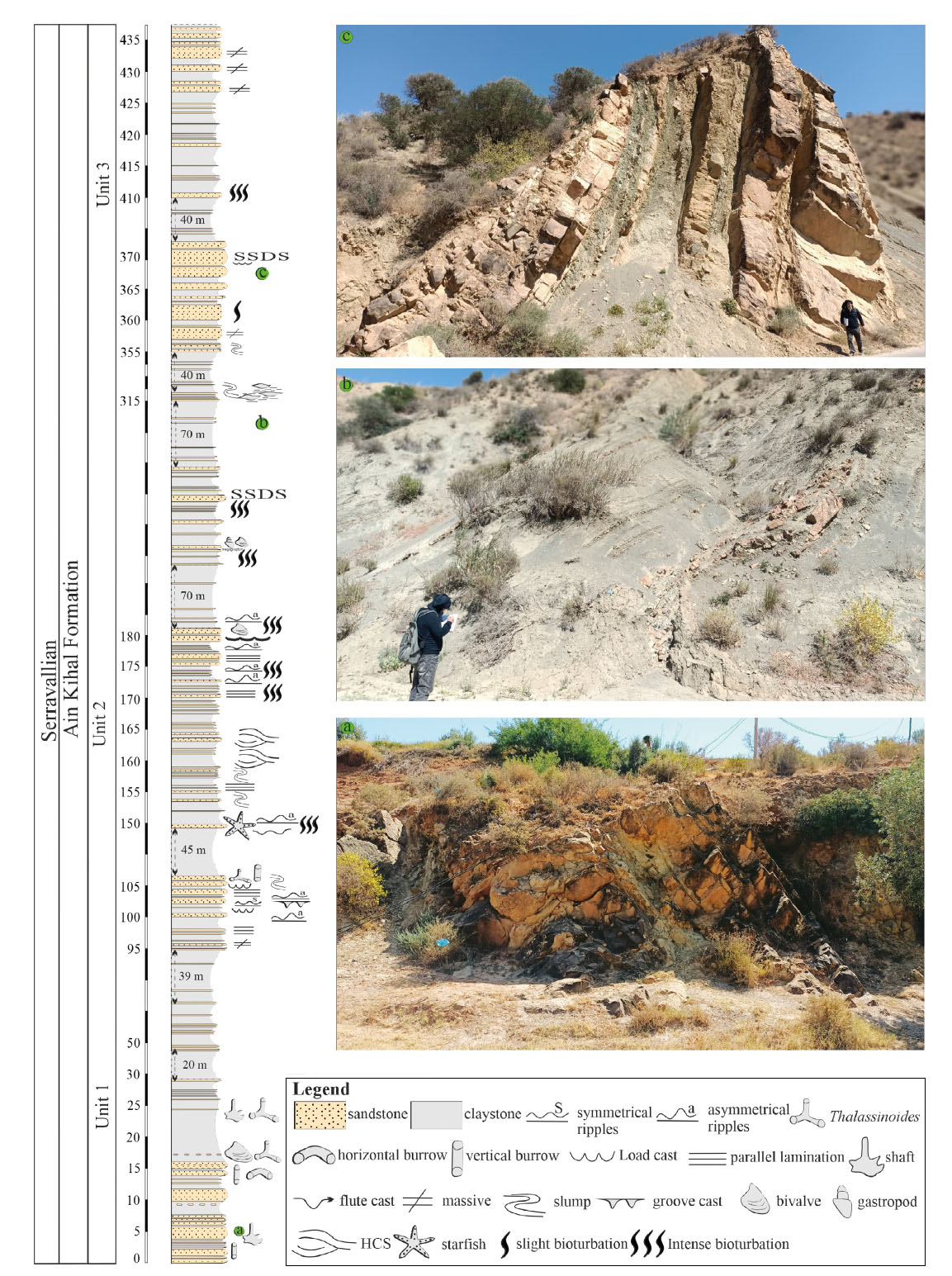
As noted above, the study area is a part of the Tafna Basin (Fig. 1A and B) and the studied succession comprises marine siliciclastic deposits, which consist of alternation (> 400 m) of yellow thick sandstone beds (0.05 to 2.5 m thick) and blue to grey marls (0.1 to 70 m). This succession represents the Ain Kihal Formation.
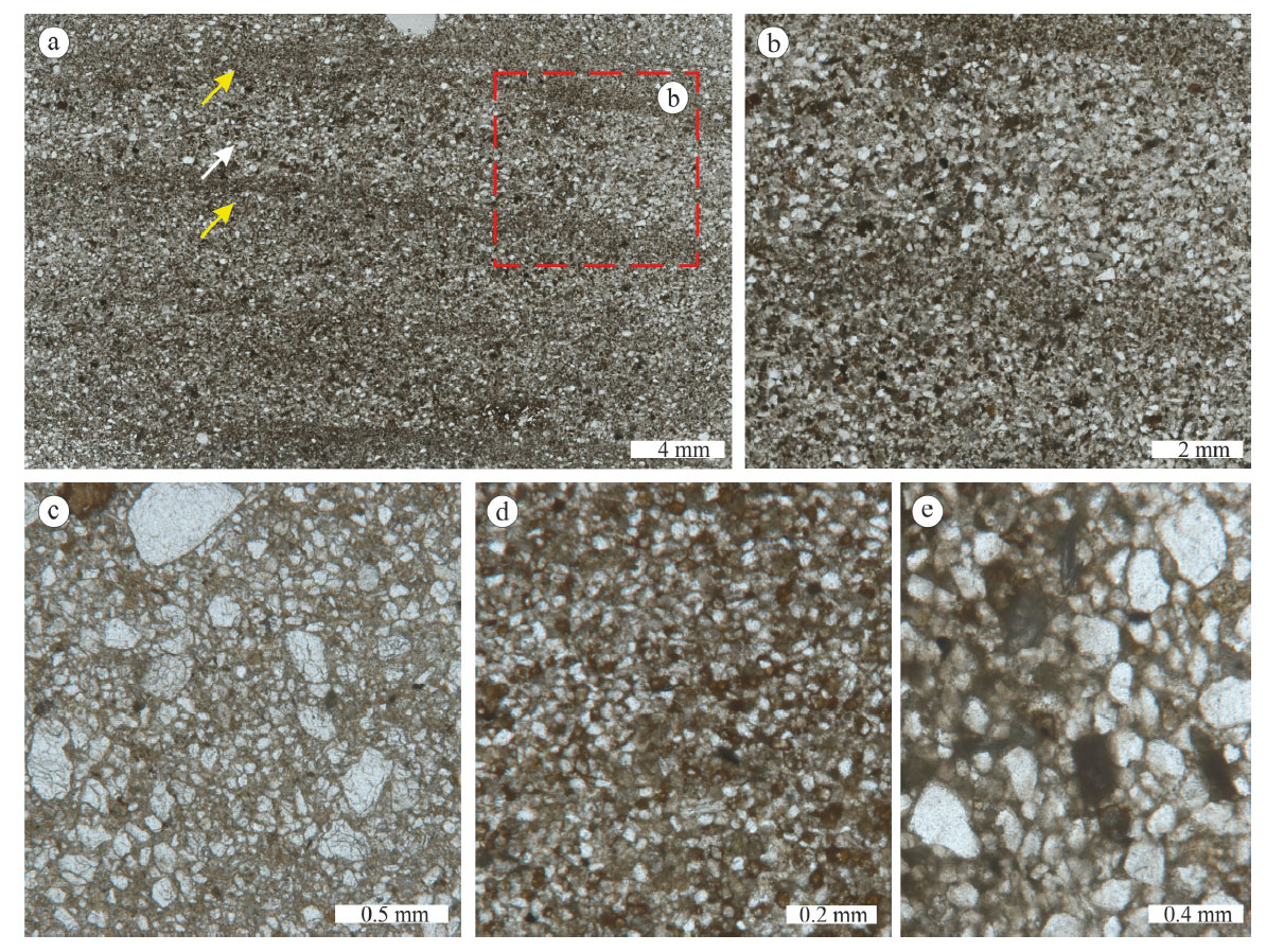
Sandstone beds are, generally, thick to very thick and some beds form lenses and are discontinuous. The succession can be subdivided into three Units; Lower, Middle and Upper Unit (Fig. 2). The lower and the upper part are barren, whereas the medium unit bears rare oyster fragments, gastropods and bivalves. The microscopic study revealed fine-medium to coarse quartz grains, with feldspar, all the studied samples are barre barren fossils, except two samples with benthic foraminifera and oyster remains (Fig. 3).
-Lithostratigraphical section for the studied Serravallian outcrop, Ain Kihal Sandstone Formation, Hadjret El Gat area (Tafna Basin, NW Algeria).
-Photomicrograph of the Ain Kihal Formation sandstones. A: alternating of medium-grained quartz layers and fine-grained quartz with clay layers. B: close-up view from A. C, D and E: poorly sorted sandstone exhibiting a mixture of medium-grained quartz grains with coarse-grained quartz.
The Lower Unit consists of very thick yellow sandstone beds at the base. The thickness of sandstone beds decreases upwards in the Unit. The blue/grey marl is very thick and contains thin to very thin sandstone interbeds. Some beds display parallel lamination with erosive bases. It is noteworthy to mention the scarcity of fossils (Tab. 1), except for some bivalve fragments at the base of the marl. Another feature of this Unit is the rarity of trace fossils (Tab. 1).
| Unit | Code | Structure | Colour and bed thickness | Sedimentary structures associations | Bioturbation index and fauna | Mecanisme | Interpretation |
|---|---|---|---|---|---|---|---|
| 1 and 2 | FLC | Load casts | 0.2 m to 0.8 m vertically 0.4 m to 1.5 m | Flame structures | BI=0 No Fauna | Liquefaction Different densities between the sand and the underlying marl. | They are probably resulted from the instability initiated by a seismic activity (Van Loon et al., 2020). |
| 1 and 2 | FFS | Flame structures | 0.1 to 0.15 m heigh and 0.08 to 0.1 m wide | Load casts | BI=0 No Fauna | Liquifaction and fluidization | Caused by load pressure downslope movement of sediments or an earthquake shock (Li et al., 2008; Shamunghan, 2016, 2017). |
| 1 | FMC | Mud clasts | Average 2 cm well sorted to moderately sorted | / | BI=0 No Fauna | Liquifaction and fluidization | Catastrophic deposition event (Li et al., 2017) |
| 1 and 2 | FPB | Pillow beds | yellowish fine-grained sandstone the longest axes 10-20cm 20-50 cm and along shortest | / | BI=0 No Fauna | Formed as a result of dewatering | Overloading, sliding or seismic shock (Roep & Everts, 1992). |
| 2 | FBPS | Ball-and-pillow structures | 0.2-0.3 m wide and 0.1-0.25m high | / | BI=0 No Fauna | Result from gravitational instability caused by density inversion triggered when dense, thick sandy sediments were deposited rapidly over less dense, water-saturated marly intervals | Interpreted as result of seismic activity (Allen, 1986; Rodriguez-Pascua, 2000; Pati & Singh, 2023). |
| 2 | FCB | Contorted bedding | up to 1.5 m thick | / | BI=0 No Fauna | partial liquifaction | Contorted bedding in sandy sediments may have been triggered by earthquake shocks (Sims, 1973; Rossetti, 1999; Pati & Singh, 2023). |
| 2 | FCL | Convolute lamination | 2 to 7 cm wide. height is between 5 and 10 cm | Pseudonodule, Dish-and-pillar structures, autoclastic breccia | BI=0 No Fauna | partial liquefaction rather than fluidization hydroplastic deformation | Contorted bedding in sandy sediments may have been triggered by earthquake shocks (Sims, 1973; Rossetti, 1999; Pati & Singh, 2023). |
| 2 | FAB | Auroclastic Breccias | They range in size from 1 to 5 cm | Pseudonodule, Dish-and-pillar structures, autoclastic breccia | BI=0 No Fauna | / | Earthquake tremors (Shanmugam, 2015, 2016, 2017). |
| 2 | FDPS | Dish-and-pillar structures | Black to gray sandstone are 8–13 cm in width pillar Pillar-bases (4-6 cm wide) | Pseudonodule, Dish-and-pillar structures, autoclastic breccia | BI=0 No Fauna | Liquifaction and/or fluidization | Earthquake vibrations (Qiao, Song, & Gao, 1994). |
| 2 | FP | Pseudonodule | Pillar-bases (4-6 cm wide) | autoclastic breccia | BI=0 No Fauna | Density divergence of unstable layers, rapid sedimentation, triggered by autocyclic sedimentary processes liquefaction | producing pillars are triggered by seismic activity (Fernandes et al. 2007; Foix et al. 2008). |
| 2 and 3 | FS | Slumps | 15-0.22 m wide and 0.06-0.1 m heigh | Pseudonodule, Dish-and-pillar structures | BI=0 No Fauna | High pore-water pressure facilitates the formation of slump Movement | Seismic shocks (Obermeier, 1996; Rodriguez-Pascua, 2000; Ozcelik, 2016; Pati & Singh, 2023). |
| 3 | FD | Dykes | 1.7 m in length average width 7 cm | Slumps | BI=0 No Fauna | Injection of liquefied or fluidized sands into adjacent sedimentary layers | Seismic shocks (during downslope movement of unlithified sediments (Mills, 1983; Moretti & Sabato, 2007; Shanmugam, 2016; Pati & Singh, 2023) Seismic shocks (The fluidized Sands flow upward through fractures triggered by brittle failure Owen, 1995). |
The middle Unit consists of very thick sandstone beds, up to 2 m. This Unit contains numerous trace fossils and sedimentary structures (hummocky cross stratification, ripple marks, gutter casts and groove casts). Body fossils are represented by bivalves and gastropods, some sandstone beds contain oyster fragments of centimeter size. Slumps and soft-sediment deformations structures are relatively abundant in this Unit (Tab. 1).
The Upper Unit consists mainly of intercalation of marls and thin sandstone beds, at the top of this Unit there are three very thick structureless sandstone beds.
The sieving of rock residue was not a success. The residue yielded highly altered foraminifera, and only the genus Ammonia could be recognised. Subsequently, a Serravallian age of studied section is based on the lithologic correlation with other sections (Aïn Kihal Formation) as well as on the previous studies (Guardia, 1975; Mazouzi, 2004). Foraminifera from the Lower Unit represented essentially by Ammonia teppeda and accessory by Ammonia beccari.
Sedimentary structures
In the studied section, lithostratigraphic data show alternation of thick fine-grained sandstone and decametric to metric marl facies. Throughout the Hadjret El Gat section, trough and planar cross stratifications are present, indicating deposition by wave processes (Greenwood & Mittler, 1985). Sedimentary structures characteristic to storm-related deposition, such as hummocky cross stratification (HCS) and swaley cross stratification (SCS) are present in Uint two (two levels of HCS). HCS and SCS are typical of storm-wave deposition in lower shoreface (Leckie & Walker, 1982). The sedimentary structure assemblage of SCS, planar cross stratification indicates deposition in a relatively deeper nearshore zone where low-energy fair-weather-wave activities prevail and allow preservation of storm-wave deposition (Leckie & Walker, 1982; Aigner & Reineck, 1982; Dott & Bourgeois, 1982; Nelson, 1982; Rosenthal & Walker, 1987; Duke et al., 1991).
In the Lower Unit of Hadjret El Gat, the sedimentary structures characteristic to high energy environment are prevalent. Such structures have been observed at the bases and/or within the sandstone facies. The structures include erosive basal shape, rip-up mudstone clasts, channel-like scouring surfaces, groove casts, gutter casts and lenticular bed geometry.
As a detailed trace fossils data will be provided elsewhere, only a brief overview is given herein. The bioturbation is common in all marl sandstone succession, and is represented by the Cruziana ichnofacies. The Lower Unit is characterised by the Cruziana ichnofacies representing by the following traces: Palaeophycus tubularis, Planolites isp., Bergaueria isp., Asteriacites lumbricalis, Phycodes isp., Lockeia isp., Kingella isp., Ophiomorpha nodosa, Quebecichnus isp. and Thallasinoides swevicus. Among the trace fossils, Ophiomorpha was made by crustaceans such as shrimps (Frey et al., 1978) in nearshore and shallow-water marine depositional environment (Boggs, 1995; Buatois & Mangano, 2011). Palaeophycus is a eurybathic trace interpreted as dwelling burrows of polychaete worms (Tchoumatchenco & Uchman, 2001) or predatory worms (Pemberton & Frey, 1982).
The middle unit is represented by Conichnus upright is usually associated with Arenicolites, Diplocraterion, Macanopsis isp., Monocraterion isp., and Skolithos and is considered an important element of the Skolithos ichnofacies (MacEachern & Pemberton, 1992; Buck & Goldring, 2003). It is typically associated with marginal marine depositional environments that experience uniform or small episodic increments of sedimentation (MacEachern & Pemberton, 1992).
The Upper Unit of Ain Kihal Formation is represented by fully marine deposits. The studied succession mostly contains yellow sandstone beds (0.05 to 2.5 m thick) alternated with grey to blackish clays (0.1 to 70 m). Sandstone beds are, generally, thick to very thick with toppened ripples with Bi = 0
Earthquake-related soft-sediment deformation structures (SSDS)
All individual SSD zones are bounded by undeformed beds from above and below (Montenat et al., 2007) (Fig. 5). The SSDS structures have gradual boundary with the underlying beds, and a sharp contact with the overlying beds. The lower contact of SSD zone is often defined by a sharp contrast in the grain size.
Various types of soft-sediment deformation structures have been observed from the Serravallian Ain Kihal Formation at the Hadjret El Gat outcrop, such as slumps, recumbent folds, convolute laminae, flame structures, water escape structures, dish and-pillar structures, pseudonodules, pillow structures, and pillow beds (Tab. 1). They all are preserved within 1.5 to 2.0 m thick sandstone horizons.
Soft-sediment deformation structures described herein occur at several horizons in the Serravallian deposits of the Tafna Basin (NW Algeria) (Tab. 1). These deposits were occasionally affected by storms. Detailed sedimentary logs of selected outcrops along with SSDS horizons are given in Fig. 2.
The stratigraphic distribution of the SSDS in the Hadjret El Gat outcrop is sporadic and variable in shape and size from one horizon to another (Fig. 2) (Tab. 1). Some horizons include up to six SSDS whereas others contain only single or two deformed beds.
Load casts (Fig. 4A and B) (Tab. 1)
Description
The load casts are the second most abundant deformation structures within the studied section. The load structures always occur at the boundary between sandstone and marl. When the sandy sediments sank into unconsolidated muddy layers, the load structures were formed. These structures occur in various sizes and shapes in the fine-grained sandstones of Hadjret El Gat outrcrop. They are hemispherical, simple, broad and rounded, often bowl-like in shape. They can be symmetrical, asymmetrical (Fig. 4A and B) or irregular in shape. They have a maximum vertical extent of 0.4 to 0.6 m and are up to 0.8 m wide in cross section. The size and shape can vary both vertically and laterally within the succession (Vertical extent varies between 0.2 m and 0.8 m. whereas, the lateral extent ranges between 0.4 m and 1.5 m). Typically, these load structures consist of intercalated sand- and marls and they do not show any internal stratification. Despite their morphological variations, different sizes, or stratigraphic level within the outcrop, the overlying and underlying beds of these load structures are always undeformed. Load cast horizons co-occur with flame and pillow structures at various stratigraphic levels.
-Soft-sediment deformation structures (SSDS) from the Middle Unit of Ain Kihal Sandstone Formation: (A) Load cast and flame structures (yellow arrows) from the Middle Unit, (B) close-up view from A, (C) close-up view from (A) displays high bioturbation of the underlying bed, (D) top of the sandstone beddisplays moderate rounded and moderate sorted mud clasts from the Lower Unit.
It is noteworthy to mention that the SSDS horizons do not show any bioturbation (Tab. 1), whereas the overlying and underlying beds are moderately bioturbated (bioturbation index ≈ 3) (Fig. 4C).
Interpretation
Different densities between the sand and the underlying marl are the main controlling factor of the deformation of sand bases in their plastic state, this led to the partial incursion of the marl in the soft overlying sand. This phenomenon is the result of liquefaction, which led to the deformation of the base of beds due to gravity-related instability (Owen, 1987; Collinson, 1994; Moretti et al., 1999; Tasgin et al., 2011; Van Loon et al., 2020). The bottom part of the upper layer (sand) tends to sink into the underlying bed (marl) in the form of rounded units leading to the formation of load casts. The load casts morphology depends on the following factors: 1) the dynamic viscosity level of the liquefied sediment layers (sand and marl) (Anketell et al.,1970; Mills, 1983; Alfaro et al., 1997) and 2) the duration of the liquefaction phase (Owen 2003; Alves, 2015). The load casts and flame structures observed in the study area display close relationship, they both are probably resulted from the instability initiated by a seismic activity. Many authors have considered seismic shocks to be the triggering agents for formation of these structures (Bowman et al., 2004; Mohindra & Thakur, 1998; Rana et al., 2013; Rana et al., 2016; Ghosh et al., 2012; Topal & Ozkul, 2014; Van Loon et al., 2020).
Flame structures (Fig. 4A and B) (Tab. 1)
Description
The flame structures are narrower and have upwards a pointed end (Fig. 4A and B). They are composed of fine-marl sediments that have intruded into the above-deformed layer of fine sand as linear to curvilinear injections giving it the appearance of a flame shaped body. They occur mostly together with load casts and are medium-sized up to 10-15 cm height and 8-10 cm wide (Fig. 4A and B). The curved laminae overlying the flamed mudstone layer follow the flame margin and take the shape of convex-upward folds above the apex of the flame. Flame structures have been documented from the lower and the middle Units, whereas they are absent in the Upper Unit.
Interpretation
The observed flame structures developed as fluid escape structures in the Hadjret El Gat area. The foundering and sinking of denser sediments triggered upward movement of underlying liquefied sediments and that cut the overlying thin bed of marl. The marl got mixed with fluidised sand and mud resulted in the formation of flame-shape body. These structures were presumably caused by load pressure, downslope movement of sediments or an earthquake shock (Li et al., 2008; Shamunghan, 2016, 2017). There is no indication of any significant load from overlying sediments and near vertical orientation of the flames argues against any genetic relation to storm sedimentary processes.
Both hydroplastic and liquefied flow can be involved in the formation of the flame structures (Tab. 2) by the upward movements of sediment due to the gravitational instability. The dynamic viscosity of the underlying marls is lower than that of the overlying sands (Anketell et al., 1970), and consequently, the diapiric intrusion of fine-grained sediments forms flame structures (Mills, 1983; Dasgupta, 1998; Alves, 2015).
Flame structures which correspond to local fluid expulsion following liquefaction in the surrounding beds (Mishra et al., 2013; Shanmugam, 2017).
Mud clasts (Fig. 4D) (Tab. 1)
Description
Mud clasts have been observed only in the lower Unit of the Hadjret El Gat outrcrop. They appear in groups. The clasts vary between 1, 5 to 5 cm in diameter, but on average they measure about 2 cm along the longitudinal axis of an ellipsoid pebble. The shape of clasts varies from elongated rounded to subrounded in cross-section, rarely subangular (Fig. 4D). These structures are associated with the thickest sandstone (>1, 50 m thick). The studied mud clasts are well sorted to moderately sorted, and without any imbrication. According to Li et al. (2017) mud clasts classification, the top-bed mud clasts could be qualified as matrix supported, moderate rounded and moderate sorted (Fig. 4D).
Interpretation
Mud clasts have been documented both from marine and non-marine settings, and the top-bed mud clasts reflect post depositional mobilisation (Stow & Johansson, 2000). The shape, abundance and sorting of the clasts (well sorted to moderately sorted) suggests that they can be ascribed to a catastrophic deposition event (Li et al., 2017). Mud clasts may have been formed in the following process; they were ripped-up or ripped-down from the host sediment into a sediment flow (e.g., Macdonald & Flecker, 2007). However, the absence of surfaces with evidence of erosion in large clasts suggests that their production was not directly associated with erosional processes (e.g., Duranti & Hurst, 2004).
Pillow beds (Fig. 5) (Tab. 1)
Description
Pillow beds occur in the lower and the middle Unit and they are usually 1.5 to 1.75 m thick. The pillows consist of dominantly yellowish fine-grained sandstone. Their dimensions are along the longest axes 20-50 cm and along shortest axes 10-20 cm.
-Pillow bed from the Middle Unit, displays highly deformed sandstone bed bounded by two undeformed sandstone beds. The sandstone-marl succession is covered by the Quaternary Alluvium.
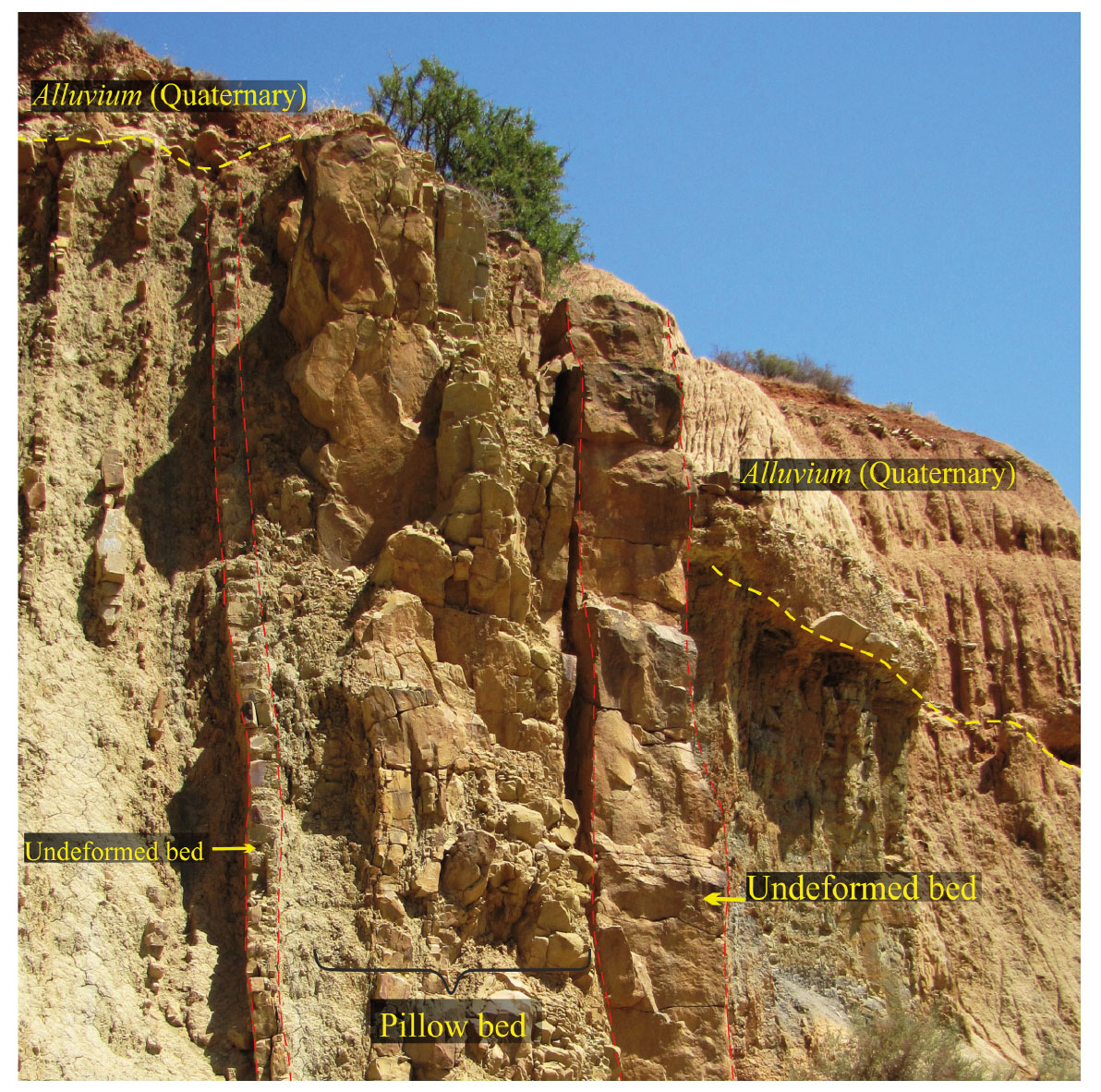
Most structures have a pillow-like or, in a few cases, a ball-like shape, and they occur roughly parallel to each other. The space between the pillows is filled with marl. The pillow beds contain load structures of sandstone, and water escape structures at the base. Undeformed sandstone beds (i.e., overlying and underlying) form boundary to the pillow beds (Fig. 5).
Interpretation
The pillow-beds have some resemblance to below described ball and pillow structures and they were likely formed as a result of dewatering (Roep & Everts, 1992). Three alternative hypotheses could explain their occurrence: overloading, sliding or seismic shock (Roep & Everts, 1992). We consider seismic origin as most likely because of undeformed lower surface of the pillow-beds, that excludes dewatering of-and loading into-the previously deposited beds. They could be the result of an earthquake with a magnitude of 6-7 on the Richter scale (Roep & Everts, 1992).
Ball-and-pillow –structures (Fig. 6A and B) (Tab. 1)
Description
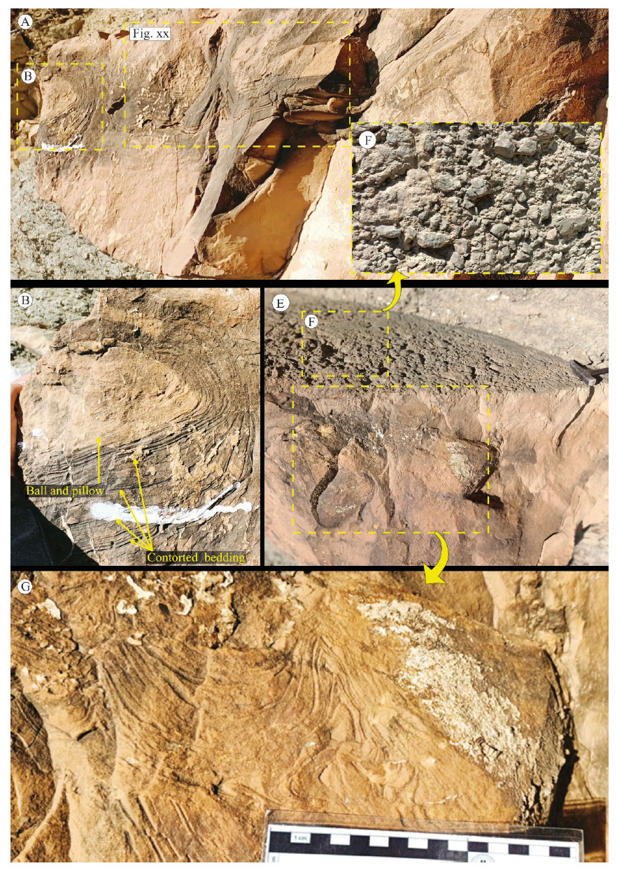
Pillow structures are the third most abundant SSDS types after slumps and load casts in the Hadjret El Gat area. They form more or less elliptical masses of fine-grained sandstone within underlying argillaceous material, or within similar material to their own composition (Fig. 6A and B). They are 0.2-0.3 m wide and 0.1-0.25 m high. These structures are load structures, which have become detached and sunk into the underlying marl and form a series of shallow bowl-like structures (Fig. 5). They are closely related to the occurrence of other load casts and water escape structures. Ball and pillow structures are more common in the middle Unit. In some cases, balls or pillows may exhibit bedding in the form of concentrically laminated ‘ovoids’ (Fig. 6B).
-Soft-sediment deformation structures (SSDS) from the Middle Unit of Ain Kihal Sandstone Formation: (A) massive sandstone bed bearing numerous SSDS, (B) ball and pillow structure associated with contored bedding, (C) Convolute laminations and autoclastic breccias, (D) close-up view from (C) displays convolute lamination, (E) close-up view from (C) displays autoclastic breccias.
Interpretation
According to Davies et al. (2004) these structures are formed as packets of one sediment type (i.e., load), sinking into another type of sediment beneath it. It is probably due to the gravitational instability of the two sediment layers. The large-scale ball-and-pillow structures are interpreted to result from gravitational instability caused by density inversion, triggered when dense, thick sandy sediments were deposited rapidly over less dense, water-saturated marly intervals (Mueller et al. 2023). The co-occurrence of some ball-and-pillow structures with other SSDS in the same beds led us to link them to a seismic activity. Similar structures have often been interpreted as result of seismic activity (Allen, 1986; Rodriguez-Pascua, 2000; Pati & Singh, 2023) and we consider these structures to be a result of seismic triggering (Obermeier, 1996; Berra & Felletti, 2011; Santos & Henrique-Pinto, 2022; Pati & Singh, 2023).
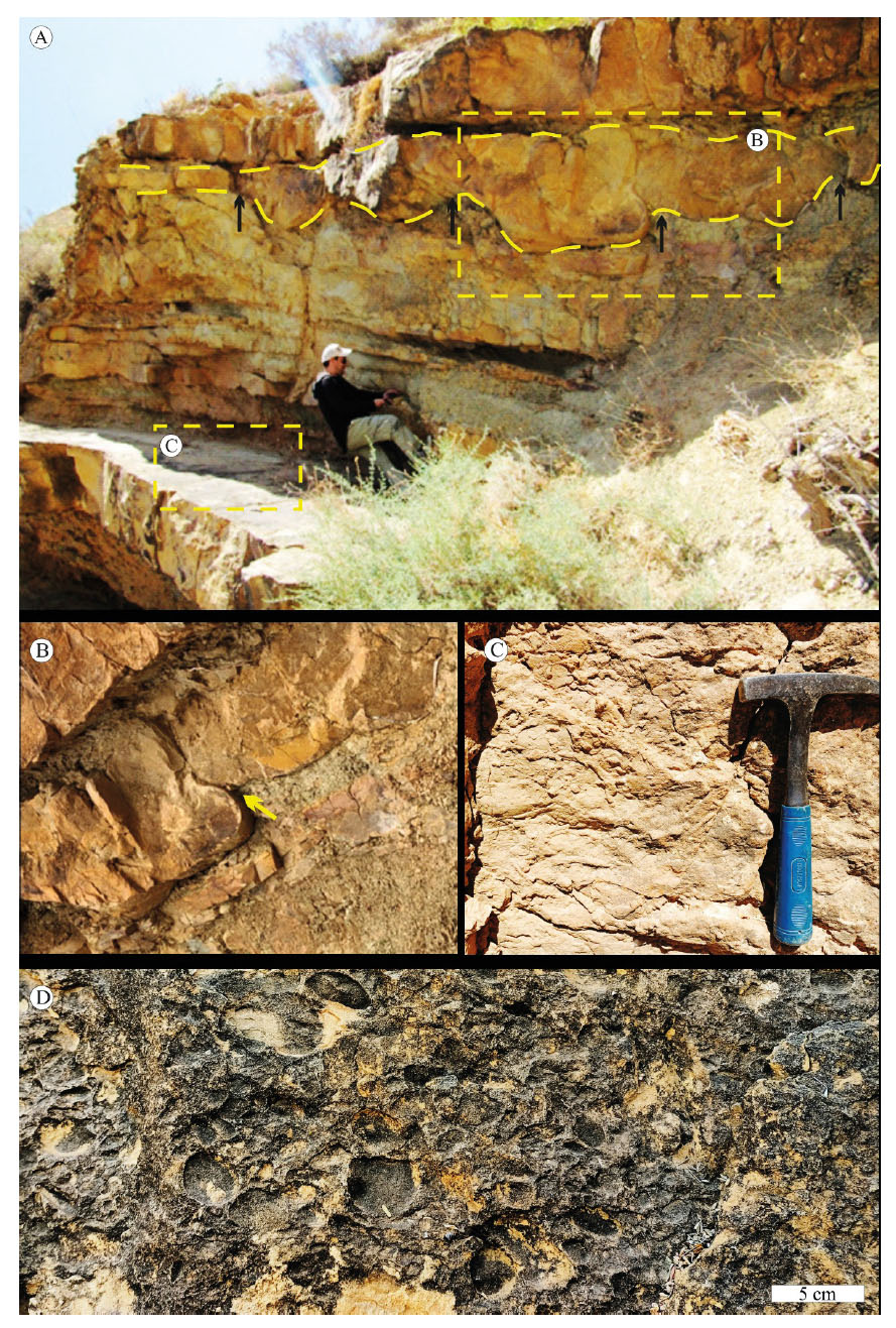
Contorted bedding (Recumbent folds) (Fig. 6A and B) (Tab. 1)
Description
This structure is preserved in a thick bed of fine sandstone with marl inter-beds in the middle Unit of the Hadjret El Gat and it displays disturbed laminae (Fig. 6A and B). There are some stratigraphic intervals, up to 1.5 m thick, that exhibit intense large-scale deformations. This pervasive deformation resembles the irregular convolute stratification (sensu Rossetti, 1999) that affects meter-sized, breccia-conglomerate to sandstone bodies. The following features allow comparison with this type of syn-sedimentary deformation: 1) highly distorted lamination, which forms either chaotic patterns or irregular folds grading into massive bedding; and 2) contorted, fine-grained, yellowish, massive sandstone lenses floating within breccia-conglomerate bodies. This contorted bedding is associated with dish and pillar as well as water-escape structures (Fig. 6A, Fig. 7A and B).
Interpretation
Contorted bedding or recumbent folds in sandy sediments may have been triggered by earthquake shocks (Sims, 1973; Rossetti, 1999; Pati & Singh, 2023) or result from slope failure (Ghosh & Mukhophadhey, 1986). Owen (1995) interpreted contorted bedding as cross stratified sediments which are product of partial liquefaction associated with current drag triggered by earthquakes.
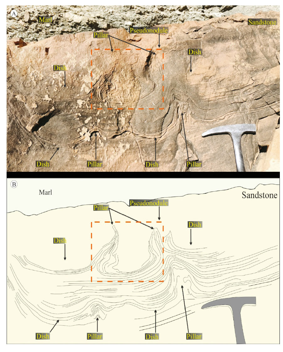
-Soft-sediment deformation structures (SSDS) from the Middle Unit of Ain Kihal Sandstone Formation: (A) dish and pillar structures from the Middle Unit, (B) sketch showing the two generations of dish and pillar structures associated with pseudonodule.
In the Hadjret El Gat area, these structures can be interpreted as result of folding deformation that took place in plastic state due to shearing drag on liquefied sand layers (Tab. 2). Slope controlled deformation is unlikely to occur as recumbent fold. Studied structures are overlain and underlain by undeformed horizontal beds with similar composition and texture, hence seismic induced deformation can be envisaged for its genesis.
Convolute lamination (Fig. 6E and G) (Tab. 1)
Description
These structures are developed in yellowish brown coloured fine-grained sandstone (Fig. 6E and G). Convolute lamination occurs in the middle Unit of sandstone-marl intercalations. The observed convolute laminations are bounded by massive sandstone within the same bed. The convoluted laminations occupy the middle part of the sandstone bed (Fig. 6A). This structure consists of regular to irregular contortions of laminated curved and deformed laminae with laterally alternating convex and concave morphologies.
The width of the convex laminae is 2 to 7 cm, and the height is between 5 and 10 cm. Convolute laminations are generally observed in a single thick layer, sometimes they are associated with other types of SSDS structures.
Interpretation
Convolute lamination develops when sediment masses are exposed to hydroplastic deformation. It is generally accepted that convolute lamination is formed during partial liquefaction rather than fluidisation of sediment (Lowe, 1975) (Tab. 2) with loss of strength in the sediments associated with dewatering processes (Lowe, 1976). Numerous alternative origins have been proposed for the convolute lamination besides the seismic origin such as, 1) current drag (Sanders, 1960), 2) liquefaction (Kuenen, 1967; Shearman, 1964; Van der Lingen, 1969), and 3) loading (Dzulynski & Walton, 1965; Shanmugam, 2015, 2016, 2017; Pati & Singh, 2023). However, the most frequent triggering agent involves elevation of pore pressures in sediment layers that may occur during sudden episodes of consolidation (e.g., earthquake tremors).
During the shaking events, the pore pressures are temporarily elevated resulting in the loss of grain-to-grain contact and temporary loss of strength because of localised expulsion of pore water (Montenat et al., 2007; Owen et al., 2011a-b). The common occurrence of convolute laminations at Hadjret El Gat suggests their origin as result of a liquefaction process. Nevertheless, the loading process as well as current drag cannot be ruled out as possible trigger agents.
Autoclastic breccias (Fig. 6E and F) (Tab. 1)
Description
Brecciation is common in the Hadjret El Gat area, dominantly represented by sandy breccias. Autochthonous breccia clasts consist of sandstone. The breccia clasts have an irregular shape, they are mostly angular, and range in size from 1 to 5 cm exceptionally up to 15 cm across. Elongate fragments are characterised by acute angle boundary and a near bedding-parallel long-axis. The pore space between fragments is filled with black-grey, siliceous cement. Locally, there is no significant dislocation between adjacent elements, resulting in breccias with well-developed mosaic (Fig. 6E and F). This structure is characteristic to the autoclastic breccias that are recorded at the top of fine-grained sandstone bed which is 1.5 m thick. The same sandstone bed bears dish and pillar structures, pseudonodules and contorted bedding.
Interpretation
The poor sorting of the breccias (Ain Kihal Formation) can be explained by their autochthonous or nearly autochthonous origin. This interpretation is supported by the local distribution of the breccia, which covers only a part of the top-bed. Earthquake vibrations can be admitted as a trigger mechanism of these kind of breccias (Du & Han, 2000; Li et al., 2008). These Serravallian autoclastic breccias display similarity to recent seismic-collapse rock documented from Jiangsu, China (Qiao, Song & Gao, 1994).
Dish-and-pillar structures (Fig. 7A and B) (Tab. 1)
Description
This structure occurs in the bed of fine-grained blackish to gray sandstone layers (Fig. 7A and B). Dish structures appear as thin, subhorizontal, flat to concave-upward, laminations (8–13 cm in width) which are separated by vertical or nearly vertical crosscutting columns (5–8 cm in high) and sheets of massive also of fine- grained sands. They are termed as pillars, and contrast with the yellowish to brownish host sandstone on either side. Dish-and pillar structures occur twice in the middle and near top-bed of fully homogenised sandstone (1.5 m) (Fig. 7A and B). They often occur together with other deformation structures (i.e., pseudonodule, convolute laminations, autoclastic breccia). The bottoms of pillars and dishes are aligned. Pillar-bases are 4-6 cm wide and their tops are almost always pointed.
Interpretation
According to Lowe & LoPiccolo (1974) pillar structures represent a vertical water escape structures formed as a response to pore pressure gradients during liquefaction and/or fluidisation (Tab. 2). Hirono (2005) ascribed the dish structures observed in clastic sediments to liquefaction process, by the flowage of particles or fluid transport by upward-directed dewatering. Fernandes et al. (2007) and Foix et al. (2008) suggested that such liquefaction and/or fluidisation producing pillars are triggered by seismic activity (Tab. 2).
Pseudonodules (Fig. 7A and B) (Tab. 1)
Description
The pseudonodules occur as semicircular to elliptical, sometimes contorted bodies in fine-grained sand masses (Fig. 7A and B). They vary in size (i.e., 0.15-0.22 m wide and 0.06-0.1 m height). Among the three types of pseudonodules described by Owen (2003), only attached pseudonodules have been observed in the studied area. The pseudonodules are surrounded by concentric laminae which are slightly deformed. They are documented from the same sandstone bed that contains dish and pillar structures, as well as autoclastic breccia.
Interpretation
Pseudonodules have been documented in various environments e.g., shallow-water settings, they are considered as the response to density divergence of unstable layers (Reineck & Singh, 1980). They reflect also rapid sedimentation, triggered by autocyclic sedimentary processes (Moretti et al., 1999; Rodriguez-Pascua, 2000). However, the pseudonodules can be as well ascribed to seismic shocks, when the detached nodules indicate sinking from overlying stratum into the underneath stratum in a liquefiable state and laterally extensive nature which suggests that overlying sediments were possibly agitated (Obermeier, 1996; Rodriguez-Pascua, 2000; Ozcelik, 2016; Pati & Singh, 2023). According to Van Loon et al. (2020) palaeoearthquake induced shock might trigger such structures.
Slumps (Fig. 8A, B and C) (Tab. 1)
Description
In the Ain Kihal Formation, the slump structures are the most common soft-sediment deformation structures (Fig. 8A, B and C). The small and large-scale complex type folds with different morphologies characterize them. The folded bed is underlain as well as overlain by undeformed beds. Slumps folding was developed in yellowish fine-grained sandstone and marl. These slumps are usually observed at meter scale (3-12 m thick) they have been observed in the middle and upper Units. Occasionally, they are horizontal and sometimes even irregular folds. Often, the deformed bed pinches out towards east.
-(A, B and C) Different morphologies of slumps from the middle and the Upper Units of the Ain Kihal Sandstone Formation, (D) clastic dyke.
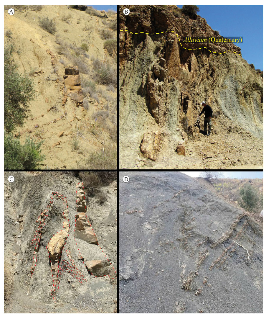
The individual layers are thrown into complex folds mostly isoclinals as well as overturned folds that consist of narrow anticlines and broad synclines (Fig. 8C). Some folds are ‘U’ shaped, broad, hinged folds with subvertical axial planes (Fig. 8B).
Interpretation
Slump folds are here considered to be formed during downslope movement of unlithified sediments sand layers over relatively more plastic layers under the action of gravity when the slope exceeds the angle of repose of sediment (Mills, 1983; Moretti & Sabato, 2007). When the stratified sediments steepen, they slip due to the increase past the angle of stability (Mills, 1983; Alves & Lourenço, 2010; Alsop & Marco, 2011; Alves, 2015). The presence of low permeability marls supporting high pore-water pressure facilitates the formation of slump movement (Mills, 1983; Moretti & Sabato, 2007; Shanmugam, 2016; Pati & Singh, 2023). In shoreface-offshore deposits studied here, this effect probably took place in the marl facies that were intercalated with the sandstones.
Dykes (Fig. 8D) (Tab. 1)
Description
Clastic dykes correspond vertically or obliquely oriented medium-grained brownish sands cutting laminated fine-grained sandstone and marl layers. These dykes were recorded from the Upper Unit of the Ain Kihal Sandstone Formation. The observed dykes can exceed 1.7 m in length (Fig. 8D) and have an average width of 7 cm. Figure 8D shows the maximum thickness at the base of the sand dyke. However, other dykes are thicker in their middle part. The original sandstone layers are relatively parallel to the sand dyke. Two different shapes of dykes were recognised; relatively rectilinear and zigzag. The sand dykes have almost the same directions. It is noteworthy to mention that the sandstone dykes occur next to the slump folds.
Interpretation
Sandstone dykes from the Ain Kihal Sandstone Formation have a finer grain size compared to the sandstone beds, which reflect a different source. The formation of dykes is explained by the injection of liquefied or fluidised sands into adjacent sedimentary layers (e.g., Qiao et al., 2017). The fluidisation happens when the sand is more permeable than the overlying sediments (Bhattacharya & Bandyopadhyay, 1998). The fluidised sands flow upward through fractures triggered by brittle failure (Owen, 1995).
The fluidised sand, which is later to be injected into fractures, is separated from the host sand bed (in the soft state) by earthquake shocks. The soft sandstone bed represents the dyke root (Sukhija et al., 1999; Rodriguez-Pascua et al., 2000; Montenat et al., 2007; Mazumder et al., 2009; Santos & Henrique-Pinto, 2022; and references therein).
DISCUSSION
Identifying the trigger agent of a SSDS is challenging (Feng, 2017a-b; Shanmugam, 2017), especially when the studied area displays the co-occurrence of syn-depositional SSDS (e.g., nodules, pseudonodules, escape water) and post-depositional SSDS (e.g., slumps, load casts) (Tab. 1). Furthermore, the sedimentologic features of Ain Kihal Sandstone Formation indicate that the deposits were occasionally affected by storms waves, HCS are observed only in Unit 2 and they are not associatedwith SSDS. This latter is suggested by the scare presence of HCS and SCS.
The “large” load casts are the result of unstable sediment with different densities between liquefied sediment (i.e., sand) and the underlying unconsolidated bed (Owen, 2003; Moretti & Sabato, 2007). The load casts size is determined by the liquefaction duration (Tab. 1). Water escape structures reflect upward movement of liquefied and fluidised sand. The water escape vertical axes represent the localised pathway of sediment dewatering. The occurrence of the following structures (water escape, pseudo nodules, convolute laminations, dish and pillar structures) (Tab. 1) at specific level from the same bed with undeformed top-bed and bottom-bed attest their syn-sedimentary origin. Otherwise, their formation took place before the deposition of the next layer of the same bed (Fig. 6). The fluidisation and liquefaction phenomena are common in the Ain Kihal Sandstone Formation; for example, the presence of mud clasts (Fig. 4) in the massive sand from above without deformation of base of the sand indicates the liquefaction of these layers. The principal cause of this liquefaction was likely a seismic activity. The rounded mud clasts within the fine-grained sandstone were moved when fluidisation occurred below in the fine-grained sand (Seilacher, 1984; Agnon et al., 2006; Sakaguchi et al., 2011). Convolute laminations are the result of fluidisation-liquefaction event and a concomitant expulsion of pore water (Brenchley & Newall, 1977; Owen, 1996; Rossetti, 1999; Rossetti & Goes, 2000; Samaila et al., 2006). It is accepted that convolute lamination took place in response to partial liquefaction and loss of strength in sediments undergoing dewatering process (Tab. 2; Lowe, 1975; Collinson, 1994).
The clastic dykes are one of the liquefaction products that form during strong earthquakes (M > 6.5) (McCalpin, 1996; Levi at al., 2006). They form when the sand source is fluidised, and these sands are more permeable than the overlying layers (Bhattacharya & Bandyopadhyay, 1998; Nichols, 2009).
The sand dykes (Tab. 1) of Hadjret El Gat area are highly inclined or nearly vertical within a horizontal group of layers, so they can be considered to be nearly perpendicular to the direction of earthquake wave propagation (e.g., Singh & Jain, 2007).
Different agents are capable of initiation of liquefaction and fluidisation leading to SSDS formation, among them gravitational forces along slopes, gravitational instabilities, shearing by current and/or biological or chemical disturbances. However, the SSDS from Hadjret El Gat area did not show any evidence of slope control (e.g., debris flows and turbidite deposits) as well as the absence of bioturbation from the deformed level refutes any possible biological control (Tab. 1). The causes of SSDS are autogenic when they involve deposition processes and allogenic when causes are post depositional, such as seismic shocks and meteoric impacts (Owen et al., 2011a). As mentioned above, beside the seismic origin, many other aseismic processes can generate the fluidisation and liquefaction of sediment, such as strong storms, rapid dumping of sediment in a gravity flow, meteoric impacts, steep slopes, tsunami waves and volcanic eruptions.
Described dish and pillar structures (Fig. 7) are water escape structures that form in unconsolidated sediments during stages of rapid deposition in shallow-water systems (Lowe, 1975). Described load casts and flame structures (Fig. 4A and B) formed in response to deposition of layer of denser sediments (sand) over on a less-dense hydroplastic layer (mud), especially during high sedimentation rate. Studied convolute beddings are centimetric crumpling and folding of parallel laminae or foreset laminae of ripple lamination. They occur in fine-grained soft-sediment in various settings from deep-marine to nearshore and fluvial environments, and they occur frequently in shallow-water. They can be produced by high sedimentation rate and seismic shaking (Reineck & Singh, 1980).
The following arguments speak against aseismic origin of the SSDS in the Ain Kihal Sandstone Formation;
1) Bioturbation is completely absent in the beds containing SSDS (Tab. 1); whereas the overlying and the underlying beds display high index of bioturbation (4 to 5) (trace fossils will be studied in details in an upcoming paper).
2) Facies analysis, displays sedimentation in environment under moderate energy, this revealed by marl dominance with very thick massive sandstone beds. The characteristics of Ain Kihal sandstone succession do not suggest a storm wave dominance. Only two levels bear small scale HSC and SCS. Another striking feature is the absence of SSDS in association with HCS, SCS and ripple marks. Evidence of tsunami waves as large-scale blocs, tsunamite sequence and amalgamated fauna is also absent.
3) The co-occurrence of different SSDS within the same level and different directions of the fluidised sand rule out the autogenic processes such as tsunami or storm waves.
4) Facies and ichnofacies suggest shore-face to offshore environment, with the absence of gravity flow deposits (e.g. debris flows, turbidities) or clast-supported conglomerates excluding the slope processes as triggering forces for studied SSDS. Furthermore, no large-scale slumps have been observed, so slip plane as possible triggering force can also be ruled out.
5) The sharp contact between the deformed beds and the overlying beds suggest that deformation occurred at the water sediment interface.
6) No impact craters have been reported in literature from the Serravallian of the Tafna Basin. Consequently, the meteoric impact is excluded as driving force.
7) Volcanic activity has been mentioned in literature from the Tafna Basin and from the Msirda Basin toward the West of the studied are, this activity started from the Serravallian (Guardia, 1975; Thomas, 1985). However, there are no signs (i.e., cinerites or volcanic rocks) of this volcanic activity in the studied outcrop. Recent published data document that the Ain Kihal Sandstone Formation is covered locally by volcanic rock (Basalt) (Benzina, 2012). Consequently, the volcanic activity is ruled out as the driving force for the formation of the SSDS.
Thus, the aseismic triggering of formation of studied SSDS ishighly unlikely. Based on the fact that the studied section lies next to a fault N30° (Thomas, 1985), the multiple earthquakes presumably were the driving force behind formation of SSDS. This interpretation is also supported by the following observation that the large scale of some SSDS (e.g., Load casts) could only be explained by an intense seismic shock (Tab. 1).
As summary, earthquakes of magnitude over than 5 degrees trigger the SSDS observed in the Ain Kihal Sandstone Formation from the Tafna Basin, northwestern Algeria. The repetitive occurrence of the SSDS indicates that the seismic activity occurred repeatedly.
CONCLUSION
Based on the detailed study of the Ain Kihal Sandstone Formation (Tafna Basin, northwestern Algeria), we conclude that the sandstone and marl alternation was deposited in shallow-water setting (lower shoreface settings) and was occasionally influenced by storm waves. The trace fossil record supports similar interpretation, as the trace fossils association is represented by the Cruziana ichnofacies.
Nine types of seismically-induced SSDS were identified in the lower and middle Units of the outcrop which include: slumps, mud clasts, autoclastic breccias, load casts structures, flame structures, water escape structures, dish and pillar structures, pseudonodules, ball and pillow structures, dykes and pillow beds. SSDS found in this area are concentrated into the fine-grained sandstones.
All the above described SSDS are bounded by undeformed beds. The latter beds are highly bioturbated, whereas the deformed bed or beds bearing SSDS are devoid of any trace fossils. The absence of trace fossils as well as fossils from the deformed bed can be explained by the stressing conditions.